Welcome to our website
Article Of The Month
Automated Testing in Blood Banks

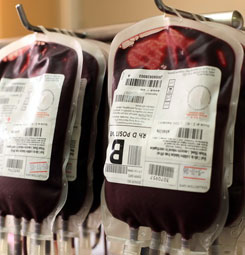
Blood banks are special places used to collect blood from people who have signed up as donors and are willing to donate theirs. These banks also store plasma, red blood cells and other products related to blood. These are all used to feed trauma units, surgery and other transfusions. In laboratories a network of expert blood bankers are working around the clock to ensure that that these blood products are safe to be used in transfusions.
But these blood banks are currently being over hauled to increase efficiency and productivity. Automation plays a key role in helping this process and there are currently many machines being used to aid this process. Over the last twenty years the number of human workers involved in this process has fell dramatically. Automation is key to this and has become a standard part of the entire process, from donation to transfusion. For more information on this subject, click here.
Manipulating Robotics

As in any design there are certain critical components that determine how a machine will be built so that these components can be incorporated properly into the machine. In our particular case the critical components are the 8 servo motors that provide the muscles for the legs. The design is based on using the most inexpensive of the servo motors that are used by radio control (R IC) hobbyists to control model aircraft control surfaces, engines and landing. The servo motors that I selected were not the fastest or the most powerful, or the smallest or the lightest — they were the most inexpensive units on the market. We need eight of them so any savings are multiplied by eight. In the USA these servo motors are available for about $12.00 (1997) each and sometimes for less (about $10.00 each) if a sale is in progress. As such these eight motors and their controller (about $50.00) form the most expensive parts used in the project. If you already own some servos or if you can borrow some for the duration of the project, you can save yourself some money. All the servos do not have to be identical but it would be helpful if they were in matched pairs to allow the legs to be made identical.
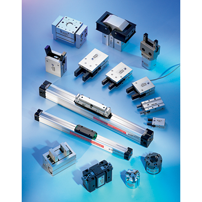
Automation Components

The robot components ready for line assembly. Xacto plastic clamps are very handy for clamping plywood parts together — I used 4 on the project. If you cannot obtain exactly the same servo motors as I have used, you will have to modify certain dimensions slightly to make sure that they fit in to the legs. The modifications are quite straightforward if you follow these instructions and there should be no problem. There is nothing magical about the dimensions I used. What I was trying to achieve keep the robot as short and as bottom heavy as possible to ensure maximum stability. It should be able to do this with the dimensions of your servos without complications. The robot components are designed to be as robust as possible and still contain the eight servo motors. The most critical location is the servo motor that controls the nutation (twist) of the automated foot in that this is the smallest part of the robot that has to accommodate a servo. This is also the joint that needs to be as backlash free as possible because small loose movements at this joint translate into big problems when tipping from side to side and when walking.
The next most critical joint is the ankle. The servos that you buy should be provided with J connectors as made by the Futaba Corporation. This is a standard connector in the model aircraft radio control trade. The pins that the controller manufacturers provide are designed to accept connectors that match this pattern. Confirm this on the controller that you purchase before you buy the servos and vice versa. Make all components in matched sets of twos and fours because it is desirable that the legs be as close to identical as possible. Start at the feet and build up to the body of the robot. None of the dimensions are critical, but you will find that it is much easier to work to drawings because that saves a lot of calculation and reworking. If you are not working to the drawings, change only those dimensions that you must to accommodate your servos.
Keep in mind that the two legs of the robot are mirror images of one another so that as you make pairs (or quads) of parts, they are to be made identical and then assembled as mirror images of one another. Carry out the following actions exactly to the letter:
- Since we will be using 3mm (Vain.) dowel bearings it is possible to drill the legs as mirror images of each other. The servos also have to run backwards from each other to perform similar duties. Six of the eight servos are mounted in the legs.
- Drill 3mm holes in the bearing locations and then sand each set. The joint holes should be drilled before you start sanding the parts and all identical pieces should be pinned
-
Assemble the torso and legs as the main assemblies. The main components of the robot ready for final assembly.
Lab Automation Input
Of the five senses, robots can use, touch, visions and sound are the three most common. The other two senses smell and taste, have been used by robots in the past but generally are not relevant to most lab automation applications. During the war on Vietnam the American Department of Defence used small portable robots to detect if there was enemy in the vicinity. How successful these machines were has not been revealed but we know that the machines did work and can surmise that the same techniques could be used to detect a gaseous chemical with a robot if this was relevant to a laboratory experiment.
Touch
Of the senses, touch is by far the most important for use with automation machines. It allows us to work with solutions to collisions and allows the exploration of the immediate environment. Using touch to explore the environment is what a blind person does and we know from experience that even rudimentary sight makes it much easier for a blind person to move about. So it is with robots. Running into objects and then backing away from them in some intelligent way is not the best way to move around.
However, touch is not restricted to motion in robotics – robots also need to know when they have grasped an object and how tightly they might have to grasp it. Other sensors that are not on the robot can be used to detect the arrival or presence of objects in the work envelope so that the robot can respond accordingly to the situation.
The Micro-Switches
The simplest input device we can provide on a robot is a micro-switch. This is an object that actuates itself to tell if the switch has been actuated. How we position the micro-switch conditions what information we will get from the actuation. This means that a micro-switch placed in front of the robot will tell us if the robot runs into something in the direction in which the switch is mounted. Since each micro-switch tells us only one thing, we may need a number of micro-switches to give us enough information to make it useful. We need to use at least four micro-switches to detect collisions, one in front, another in the back and one on the left. For some applications, we may need as many as eight switches to give us more resolution – the exact number will depend on the shape of the robot, the directions in which it moves and its environment. We do not need micro-switches where they are not likely to be actuated. A robot that can move forward only, does not need any micro-switches behind it.
Photo-Transistors
Photo-transistors can detect frequencies in and near the light and heat spectrums. The frequency does not have to be within the visible light spectrum. Infra-red frequencies are used by a large number of photo-transistor detectors and using light we cannot see makes the system less distracting to us (as the devices go on and off). A photo-transistor can be used either as an on/off device or as a modulated device. When we want on/off control we usually place the LED directly across from the photo-transistor and detect the signal if the light beam is broken. On most face-to-face installations we are looking for a flag or other device that comes between the two devices. Limit switches and similar devices are created in this way and very useful when it comes to lab
